WEEK 6
Electronics & Open Design
Class Component Sprint
In pairs, you will spend Tuesday afternoon and Wednesday to get at least two (but rather more) new components working and document and share successful code, links and circuitry; please see the documentation details below. You are very much encouraged to find, use and share online resources for this assignment.
On Friday, each team will test the documented components of (at least) one other team (decide beforehand, no doubles), using only their documentation as their guide. On your own documentation page, use at least 100 words to describe how each test went and share suggestions or mistakes with the other team so they can repair or improve their documentation. During Interface week (coming up next) we will use sensor values to make data visualizations using the Processing platform.
Friday 10:00 bonus lecture by Wouter: Up your skills with next level electronics!
ASSIGNMENT
Making Groups
For the assignment from this week i'm collaborating with Anna Schiffels. For the first exercise we got 4 papers with information and a few components to work with to give us a better few about electronics.
Getting to know electronics...
//Capacitive Soil Moisture Arduino Code
void setup() {
Serial.begin(9600); // open serial port, set the baud rate as 9600 bps
}
void loop() {
int val;
val = analogRead(A0); //connect sensor to Analog 0
Serial.println(val); //print the value to serial port
delay(1000);
}
Sensor:
Discription:
Specifications:
Capacitive Soil Moisture Sensor v1.2
Capacitive Soil Moisture Sensor v1.2
This capacitive soil moisture sensor is distinguished from most resistive sensors on the market and uses capacitive sensing to detect soil moisture. The problem that the resistance sensor is easily corroded is avoided, and its working life is greatly extended.
Operating voltage: 3.3 VDC
Output voltage: 0 ~ 3.0 VDC
Interface: PH2.54-3P
Size: 98 x 23mm (LxW)
For our first assignment we got a few components to practice with. I think this was very helpfull, because it was an easy way to get to know electronics and the components. By the use of outlines and symbols it was easy to understand how to use the components. We used copertape as a conductive material.
Resistor
LED
LED
Dimmer
Multimeter
Battery 3V
What did i Learn?
You can do it!
It is very important that everyhting is conected so the power
is able to get through.
Inside the LED it is possible to see wich side is positive and which one is negative. The bigger part is negative!
The resistor is for power distribution.
The black tape is a dimmer. The harder you press , the less power is going through!
Workshop Soldering...
In the morning of March 12 we got a little workshop in Makerslab about how to solder elektronic components.
Before you start soldering, it is important to turn on the soldering machine so it can heat up. The soldering pen can heat up to almost 400 degrees.
It is very important to turn on the vacuum cleaner while soldering to get rid of the fumes that excist during soldering. The sponge must be wet at all times while using the soldering pen to wipe off the tin.
The best way to solder the electronic components is by placing the soldering pen on both the pin and the surface where the tin will flow to. The tin wire must be held against the soldering pen so that it can melt.
The soldering paste is an aid. Solder paste is a flux for soldering. This ensures that the solder surfaces do not oxidize during soldering and that the molten solder flows properly onto the surfaces. You can whipe the paste on by using a brush.
It is smart to solder the first and the last pin first so the pins can't move anymore.
If you use to much tin while soldering, use coperwire to get rit of the excessive tin. When you reheat the tin on the pin with the soldering pen the coperwire will suck excessive tin up in seconds.


Actuator: Laser
Focused light beam
Sensor: Capacitive soil moisture sensor.
The amound of moisture in the ground
Now for real!
After the assigments on paper we got to work with the real breadboard.
After the video that was shown in class from Massimo i learned that the breadboard is divided in a specific structure. The blue and red lines are the direction of the conections between the + and - axes. The connections between the letters a to j are perpendicular to the axes of the + and - axes. It is very important that everything is contected in the right order otherwise nothing will work.
Starting with the real assignment...
For the assignment we had to pick an actuator and a sensor.
A sensor is an artificial version of what is called a sense in biology. Most sensors are electronically or mechanically implemented, software and 'virtual' sensors are also possible. ... A sensor measures a physical quantity. An actuator is complete system for checking something and responding to these observations consists of the following three parts: Sensor: this is the input of the system, a mechanism is used to make an observation here. This observation can be, for example, the ambient temperature. For a sensor you use the analog side of the chip, for the actuator you use the digital side of the chip. The amount of Voltage depends on the sensor or actuator.
Datasheet
Buy here
Tutorials
MINOR
MAKERSLAB
2019
QUICK NOTES:
VN:
3V3
GND:
S:
A0:
D0:
5 Voltage
3 Voltage
Ground
Signal
Analog
Digital
Before i started connecting everything I had to download Arduino and install the port we were going to use for the USB.
If i want to connect the Sensor to the chip i will have to use the male - female wire combination.
To connect the sensor to the breadboard we need the male-male wire combination.
The Black wire is
registered als GND. (-)
The Red Wire is
registered as VCO. (+)
The Yellow is
registered as AUOT (Analog)
Schematic
Breadboard
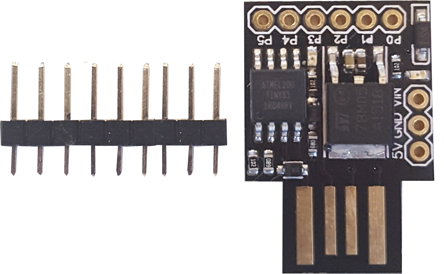
KY-008 Laser Transmitor (Documentation from Anna)
Buy Here
Datasheet
Actuator:
Discription:
Specifications:
KY-008 Laser Transmitor
This small laser transmitter module works on 5V. The laser outputs a beam of 650nm (red) of approximately 5mW. Connect this module to a motor as an interactive laser pointer. By moving the laser quickly, it is also possible to make a simple projection.
PCB
Working voltage: 5V.
650nm
Tutorials
Fritzing it is...
// KY-008 Arduino Code
int laserPin = 10;
void setup ()
{
pinMode (laserPin, OUTPUT); // define the digital output interface 13 feet
}
void loop () {
digitalWrite (laserPin, HIGH); // Turn Laser On
delay (1000); // On For Half a Second
digitalWrite (laserPin, LOW); // Turn Laser Off
delay (500); // Off for half a second
}
1. Arduino or Node MCU
2. one Laser Transmitter Module (available here)
Wiring Setup: (not much to do here either)
1. connect VN pin (5V) from the board with the middle pin (through breadboard)
2. connect GND from board to the pin with the minus next to it (through breadboard)
3. connect the D6 pin from board with the last pin on the Laser (has a S next to it, through breadboard)
NOTE: There are some unnecessary detours on the fritzing sketch, if you have the right cables male/female, you could skip using the breadboard e.g. when making the connection for the signal.
Collaborating
Anna helped me to get through the electronics. In the beginning i didn't really knew what i was doing but with the help of Anna i finally understood how to connect the sensor.
For the assignment we were supposed to switch our components with someone else, so Anna took the components with her. At Material Experience in Rotterdam Anna gave my components to Audrey. But i haven't seen or heard from Anna on Material Experience so i never got the components to test them out.
How to connect...
How to connect...
Connect the USB kable to your laptop and connect the other side to the Node MCU.
Extend the yellow wire by using a mal/female wire. ( I used the same colors to extend the wires to avoid confusion. Connect the Yellow wire from the Sensor to the A0 pin from the Node MCU.
(The yellow wire sends the signals)
Extend the red wire by using a male/male wire. Connect the red wire to breadboard and put it in the ''+'' side.
(The red wire is the Voltage)
Than u use another red wire (male/female) to connect the breadboard to the Node MCU. Connect this wire by placing it in the same row as the other red wire. The female part of the red wire is connected to the VN pin from the Node MCU. (VN is 5V)
Extend the Black wire by using a male/male wire. Connect the black wire (GND) to the breadboard in the ''-'' section.
Than u use another black wire (male/female) to connect the breadboard to the Node MCU. Connect this wire by placing it in the same row as the other black wire. The female part of the black wire is connected to the GND pin from the Node MCU.
(GND means Ground, so -)
NOTE:
There are some unnecessary detours on the fritzing sketch, if you have the right cables male/female, you could skip using the breadboard e.g. when making the connection for the signal.
1.
2.
3.
4.
5.
6.
Look how the value changes when you put the Capative Soil Moisture Sensor in the water!
Working with Anna went very well in the beginning. I had a lot of trouble understanding the electronics. Anna understood it faster than I did, and then explained it to me. For the assignment we had to change our code and sensor with someone else and test them. Anna took my parts and gave my sensor to Audrey at Material District in Rotterdam. Without telling me, I suddenly got a message from Audrey that she had my sensor, and that Anna had her sensor. I didn't see Anna myself at Material District and she didn't contact me as well. Communication is very important to me, because I don't like unpleasant surprises.
In general the cooperation went well, but I did notice that if Anna could go home she would be gone. And sometimes I would have liked a little bit more help. But fortunately I managed to do it on my own.
HOME
COLLABORATIVE LEARNING
MAKER SKILLS & ATTITUDE
I've figured out that electronics isn't really my thing. Luckily by physics I understood a bit what we were doing, but after a while it all fell into place.
Schematics is a simple representation of your electronic circuits.
A resister is the distribution of electricity, and allows small doses to pass through.
Everything has to be properly connected or it won't work anyway.
The more light a LEd gives, the greater the Voltage is that goes through it.
In some cases you don't even need the breadboard and this will cause undesirable detours.
On the breadboard you connect the horizontal lines (+ and -) with the vertical lines in the middle (letters a-j).
An actuator turns electricity into something you can see-> output.
A sensor measures something.
-
-
-
-
-
-
-
-
-